Week 8 Fillets/ Chamfers, Loft and shell.
In this week's exercises we were to model more complicated rectilinear solid shapes in Solidworks, using Features such as Fillets, Chamfers, Loft and Shells.
Troubles found with building these solids was that there were many ways you can go about to create them. The issue with this was that you will get a variance in the volume of the finished solid yet still have the same mass. I believe this exercise was to build our awareness of what happens when using different methods to build. This has an effect on overall volume which can be out by a couple of cubic millimeters.
When using Fillets and Chamfers in the build of some of the solids, you had to be aware of what order you put them in. The order of which you put different size fillets in will effect the finished appearance and may not look correct.
Sunday, 18 September 2016
Wednesday, 7 September 2016
Week 7 Assemblies


In this weeks exercises we were introduced to Assemblies. It gave us the opportunity to
- Create simple assemblies in Solidworks.
- Create an exploded view of an assembly.
- Create a technical drawing containing an exploded view and a bill of materials.
P7.1
in this exercise we were to firstly create this solid part and then create multiple assemblies using various kinds of mates to join parts together.
P7.1 Part

P7.1 Assemblies
The problems faced when mating certain parts is the orientation of the part. At least one part has to be fixed so you can rotate the other part. Doing this makes mating easier.

P7.2 These exercises introduced us to putting in a description when saving the part. This discription will come in handy when a Build of Material is needed in the Technical Drawing. The Bill of Material also introduced us to the Balloon Annotation tool. This identifies each part corresponding to the Bill of material.
P7.2.1

P7.2.2

P7.2.3

P7.2.4 Assembly

P7.2 Exploded View. Technical Drawing. Build of Material/Balloons

P7.4 Using the same parts above to create a different assembly

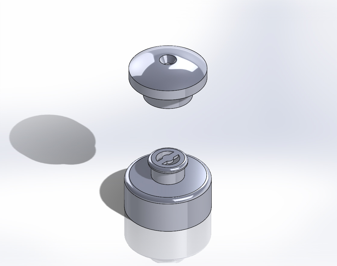
Exercise P7.5 we had to create the following parts and then create an exploded view of the assmbly
P7.5.1 Slide

P7.5.2 Cap

P7.5 Exploded Assembly
Week 6 Orthographic Views modelling and drawing exercises
P6.1
In this exercise we were introduced to creating our own AS1100 drawing template from scratch.
To create our own drawing Template we find the Standard Sheet Formats in Solidwork. File>>New>>Templates>>Drawing. In the pop-up window we make sure the 'Only show standard formats' is selected. Chose the size paper( in this case it is A3(ISO)). The standard sheet format given can be changed or edited by right clicking on the drawing plane and scroll down to Edit Sheet Format. Here you are able to change and add notations where needed and images of company logo. To ensure the sheet is in the current AS1100 drawing standard and is in Third Angle (Right click on Sheet1 in the feature manager >> Type of Projection>>Properties>>Third Angle. Once I was done with editing my sheet template, I right click on the drawing plane and select 'edit sheet format'. I Saved this drawing as my template for use in future drawings. Do this by going to File>>Save Sheet Format. Name your drawing sheet as yoursurname_yourfirstname A3 Template. Here is my drawing template.

In the following exercises for this week we were given a few solid models to put into drawings. By using our template created we are able to model them. These exercises introduced us to inserting orthographic views and experimenting which views can be used to show all or the most important information.
P6.2

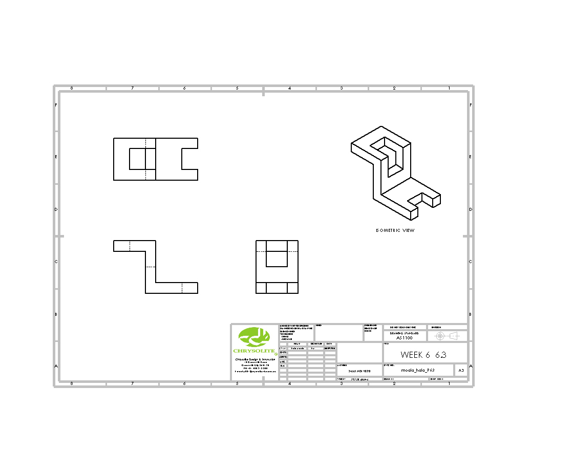
P6.3
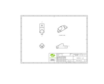
P6.4

P6.5

Wednesday, 24 August 2016
Week 5 Features
This week's tutorial and exercises gave us opportunities to utilise and familiarize ourselves with other basic Features in Solidworks.
Such as revolve, loft, sweep, Linear pattern, Fillets.
Appreciate some of the shortcuts and capabilities available in Solidworks.
Understand that there are more than one method of producing a solid model in Solidworks
Exercise 5.1a: The Stepped Shaft


I then sketched on the centre face or the hub face to create an Extrude Cut through all.


This week's tutorial and exercises gave us opportunities to utilise and familiarize ourselves with other basic Features in Solidworks.
Exercise 5.1a: The Stepped Shaft

Creating the stepped shaft, I used the Front Plane. Sketched half of the profile and used the Revolved Boss/Base feature to revolve the profile around the x-axis to form a solid.

Once the solid model is made, by using the Fillet feature I created 2 fillets. I selected the necessary edge and added a radius in.
Exercise 5.1B gave us another way of creating the stepped shaft. Sketching in the complete half profile (with fillets) in the drawing and then revolving around the x-axis.

To conclude the two exercises above, it shows that you could add features as a sketched entity or you can add it as a feature later. Which of course gives you the same result.

Exercise 5.2 was to create a 120 mm diameter sphere. To create the sphere, I had sketched a semi circle using the Arc tool and revolving around the y-axis using the Revolved Boss/Base feature.


Exercise 5.3
I used numerous features to create the V-grooved Pulley.
First I sketched a quarter of the cross-section of the pulley.
Using the Mirror entity tool to reflect on the y-axis to make the top half of the cross-sectioned profile. I then used the Revolved Boss/base feature to revolve the profile around the x-axis to form the solid model.

I then sketched on the centre face or the hub face to create an Extrude Cut through all.

And the finished product as shown below with the material set to Cast Carbon Steel.

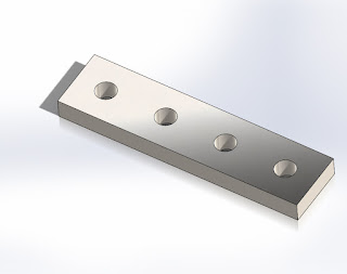
Exercise 5.4 Adding bolt holes to the Steel Beam created in exercise 4.4
I sketched a single hole with the given dimensions on the face of the beam. Then I used the Linear Pattern tool to create the rest of the holes. Using the Mirror entity tool to reflect the pattern on the other end of the steel beam using the midpoint(y-axis)
.


Exercise 5.5 Creating a 300mm hacksaw blade.
Using the Slot tool to create my sketch then used the Extrude Boss/Base to create the blank solid. I sketched one blade teeth on the face of the blank solid and Extrude Cut. I then used the Linear Pattern feature to patterned the saw blade teeth cut 300x.


Exercise 5.6 Using the Loft feature.

To create the solid model above we had to create two planes using the Reference Geometry feature. In this feature you are able to set the distance between planes. We were able to sketch a square profile on the Top Plane and a circular profile on a second plane(renamed as the circle plane).
This enabled us to use the Loft feature to create a solid between two sketched profiles. I then added a extrude cut to the face of the lofted solid.


Exercise 5.7 Swept Boss feature
In this exercise we were to use perpendicular planes to create a sweep.
Here I used the top plane to sketch the profile of the sweep. Then I used the front plane to draw the profile of what I would like to sweep. Instead of drawing 2 separate circles to create the thickness of the profile to be swept, I used the Thickness options tab in the Swept boss/base feature.


Wednesday, 17 August 2016
Week 4 Sketch Entities and Tools
This week we learnt that there are many different ways to create a sketch to form a solid part. Using different sketch entities and tools we are able to come to the same solution. It helps to ensure all relevant relations are added to entities.


This week we learnt that there are many different ways to create a sketch to form a solid part. Using different sketch entities and tools we are able to come to the same solution. It helps to ensure all relevant relations are added to entities.
Exercise 4.1 Introduced us to the Trim Entities tool. This tool is effective when you need to remove unwanted/unnecessary lines or entities. Clicking on the sketch and dragging across with the cursor will remove them.
The issue I had using this tool is that you must be careful after you have trimmed an entity. Insure that you have trimmed all unwanted lines or entities and double-check that your sketch is correct and has no faults. Keep in mind some entities overlap more than once.
Working this exercise I thought I had trimmed all the entities that I did not want but had missed a few spots. With the result of this I was not able to extrude the sketch. So I had to go back and Edit Sketch and finely search and fix the entities.

Exercise 4.2 took us back into Adding Relations. If you look closely at the below drawing there is a few Tangent relations icon where the straight lines meet the curves. Adding a Tangent Relation gives us a smooth transition from a straight line into the curve. It is important to understand the difference between the sketch below and the sketch above.

Exercise 4.3 introduced us to the Slot tool. Instead of having to use 2 circles and 2 lines to form the sketch below, it is faster to simply use the Slot tool.

Exercise 4.4 let us play more with the Mirror Entities tool to form a solid such as a Steel Beam

In this Sketch I started with the top-left quadrant. Using the Mirror Entities tool I was able to mirror the top left quadrant on the vertical centre line. Then mirroring the top sketch on the horizontal line.

Exercise 4.5 gave us more opportunity to use the Trim Entities tool to create the bottom sketch. I find that using construction lines and centre lines are helpful when creating a radius from a point in space.

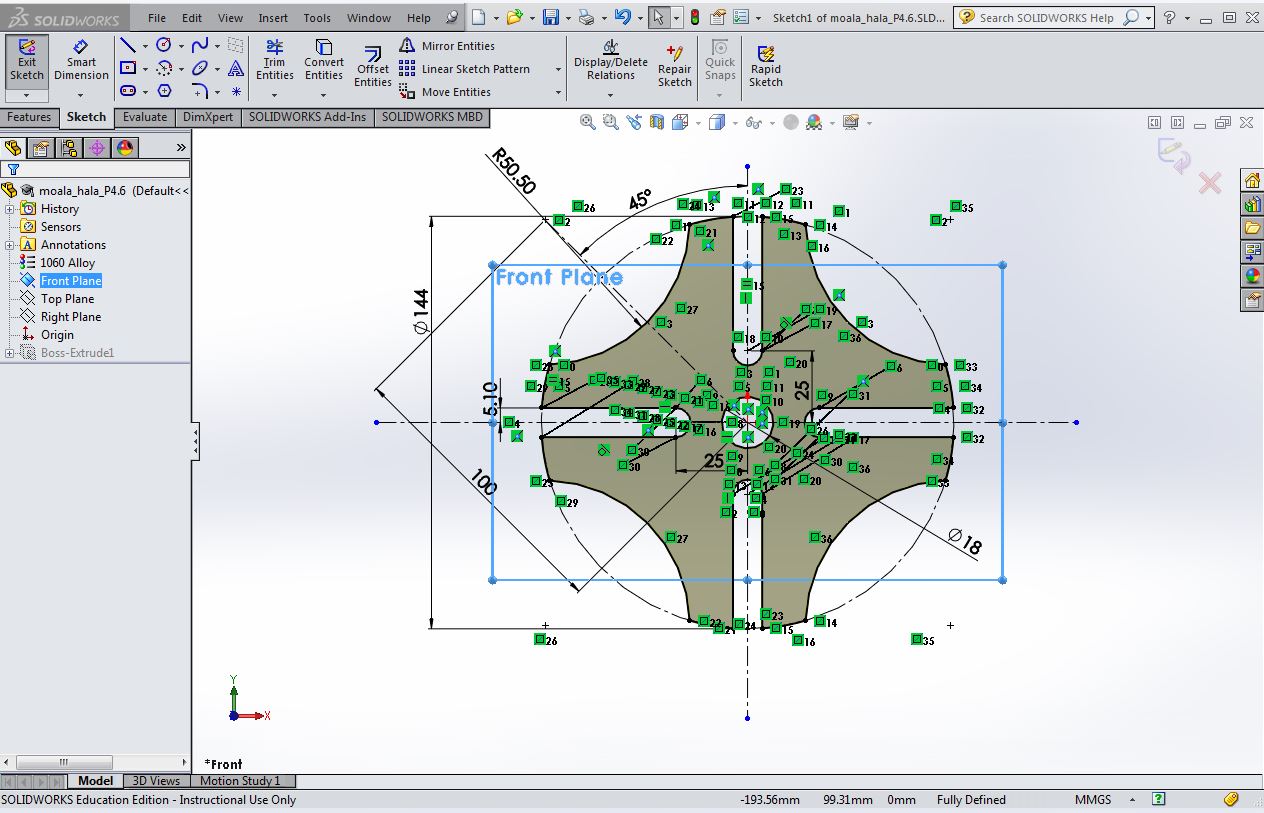
Exercise 4.6 combined all the skills learnt in the previous exercises. Using a combination of Trim Entities and Mirror Entities we were able to create the solid model below. Other tools used were the Centre-point Arc tool.

After assessing the Solid model I found I could have also used the Slot tool.
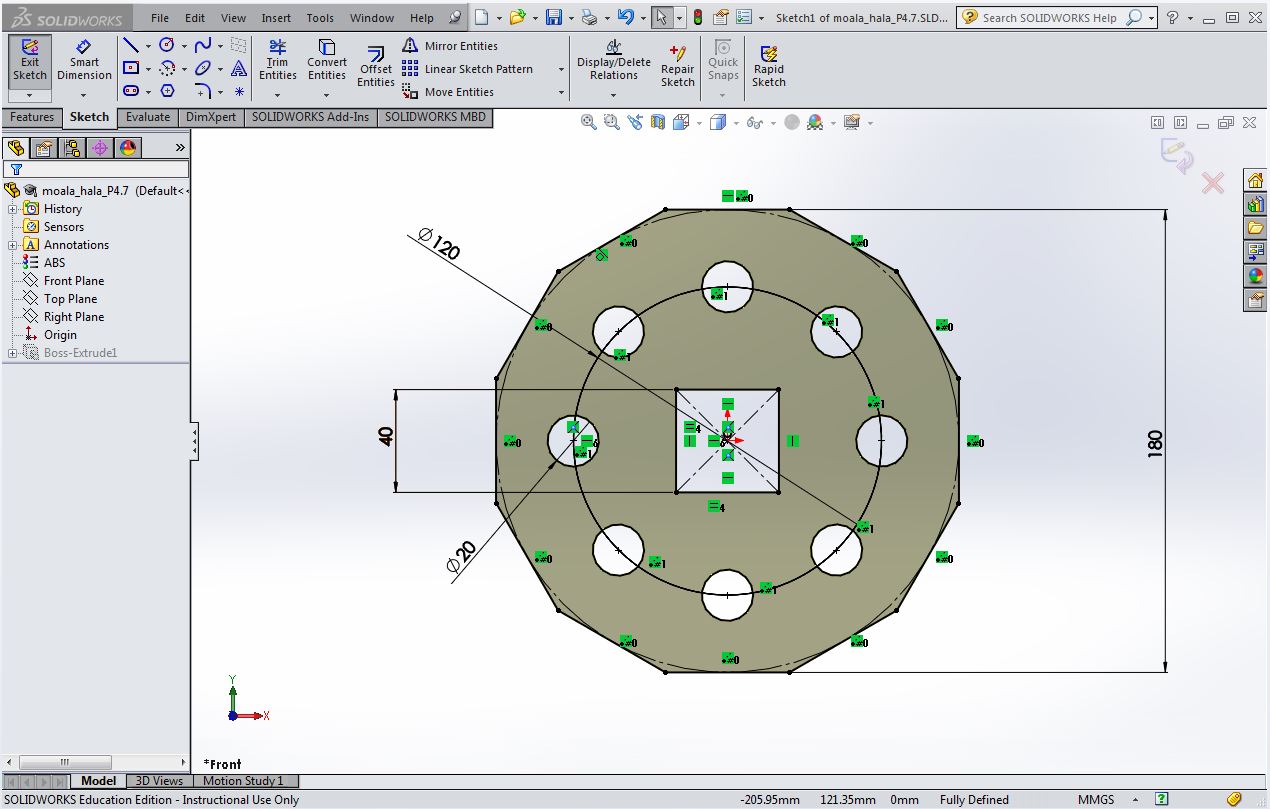
Exercise 4.7 introduced us to the Polygon tool. When creating this polygon we were able to set how many edges we wanted. This exercise gave us the opportunity to use the Circular Pattern tool.

Thursday, 11 August 2016
Week 3 Getting Started with Solidworks
In this week's tutorial we were to familiarize ourselves with the various terminology used in solid modelling.The exercises for the week gave us an opportunity to start building solids from a given 2d drawing. It also gave us the understanding of how important it is to have our drawings and sketches fully defined, as this step can alter the properties of the part or solid.
Some of the terminology used in solid modelling include the following:
Vortex
Face
Edge
Axis
Plane
Origin
Mass Properties
Fully Defined/Under Defined
Feature
Sketch
Relations
To build our first solid we had to open a New Part in Solidworks. To start sketching you have to select a Plane that you will like to draw on first, and to remember it is best to start your Sketch from the Origin. Starting the Sketch from the Origin(x0,y0,z0) ensures we have a known reference starting point and all Relations can be defined. Adding Relations to entities( Lines, Points) helps control the sketch. Using Smart Dimension adds dimensions to the drawing.
Steps used to create this solid:
Sketch your 2d profile using the Line tool
Add Relations
Use Smart Dimension to add dimensions
Exit Sketch
Select Extrude Boss to turn sketch into a solid Feature by setting the thickness

NB: It is important that the drawing is Fully Defined( All Lines are Black). It ensures all the information to make this part is communicated, and ensures that no part of the drawing can be altered by accident being Under Defined( Blue lines).

Making small changes to dimensions and the thickness of the Feature alters the mass of the part. Refer back to the note of how important it is to have a Fully Defined sketch. To find out the mass of the part we select the Evaluate tab and select Mass Properties.

Apart of this weeks exercises we also learnt how to Edit Material to change the part's properties. Some parts were made of Plastic ABS to Aluminium 1060 Alloy which also alters the mass property of the part.

The last exercise introduced us to the Linear Sketch Pattern and Circular Sketch Pattern tool. This tool is handy if there are parts with repetitive features.


Subscribe to:
Posts (Atom)