Week 8 Fillets/ Chamfers, Loft and shell.
In this week's exercises we were to model more complicated rectilinear solid shapes in Solidworks, using Features such as Fillets, Chamfers, Loft and Shells.
Troubles found with building these solids was that there were many ways you can go about to create them. The issue with this was that you will get a variance in the volume of the finished solid yet still have the same mass. I believe this exercise was to build our awareness of what happens when using different methods to build. This has an effect on overall volume which can be out by a couple of cubic millimeters.
When using Fillets and Chamfers in the build of some of the solids, you had to be aware of what order you put them in. The order of which you put different size fillets in will effect the finished appearance and may not look correct.
Sunday, 18 September 2016
Wednesday, 7 September 2016
Week 7 Assemblies


In this weeks exercises we were introduced to Assemblies. It gave us the opportunity to
- Create simple assemblies in Solidworks.
- Create an exploded view of an assembly.
- Create a technical drawing containing an exploded view and a bill of materials.
P7.1
in this exercise we were to firstly create this solid part and then create multiple assemblies using various kinds of mates to join parts together.
P7.1 Part

P7.1 Assemblies
The problems faced when mating certain parts is the orientation of the part. At least one part has to be fixed so you can rotate the other part. Doing this makes mating easier.

P7.2 These exercises introduced us to putting in a description when saving the part. This discription will come in handy when a Build of Material is needed in the Technical Drawing. The Bill of Material also introduced us to the Balloon Annotation tool. This identifies each part corresponding to the Bill of material.
P7.2.1

P7.2.2

P7.2.3

P7.2.4 Assembly

P7.2 Exploded View. Technical Drawing. Build of Material/Balloons

P7.4 Using the same parts above to create a different assembly

Exercise P7.5 we had to create the following parts and then create an exploded view of the assmbly
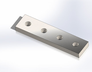
P7.5.1 Slide

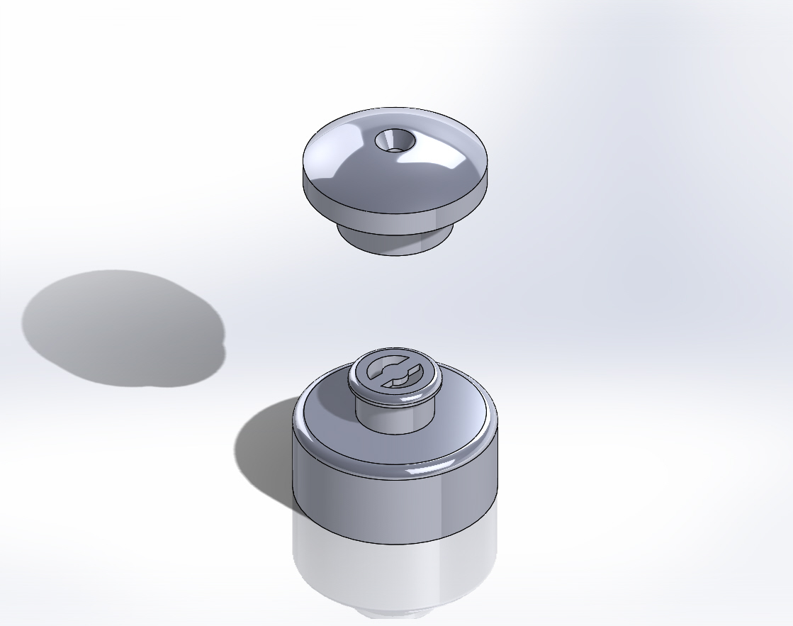
P7.5.2 Cap

P7.5 Exploded Assembly
Week 6 Orthographic Views modelling and drawing exercises
P6.1
In this exercise we were introduced to creating our own AS1100 drawing template from scratch.
To create our own drawing Template we find the Standard Sheet Formats in Solidwork. File>>New>>Templates>>Drawing. In the pop-up window we make sure the 'Only show standard formats' is selected. Chose the size paper( in this case it is A3(ISO)). The standard sheet format given can be changed or edited by right clicking on the drawing plane and scroll down to Edit Sheet Format. Here you are able to change and add notations where needed and images of company logo. To ensure the sheet is in the current AS1100 drawing standard and is in Third Angle (Right click on Sheet1 in the feature manager >> Type of Projection>>Properties>>Third Angle. Once I was done with editing my sheet template, I right click on the drawing plane and select 'edit sheet format'. I Saved this drawing as my template for use in future drawings. Do this by going to File>>Save Sheet Format. Name your drawing sheet as yoursurname_yourfirstname A3 Template. Here is my drawing template.

In the following exercises for this week we were given a few solid models to put into drawings. By using our template created we are able to model them. These exercises introduced us to inserting orthographic views and experimenting which views can be used to show all or the most important information.
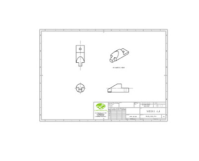
P6.2

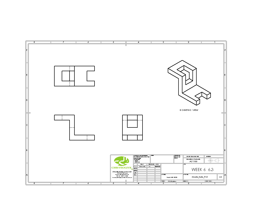
P6.3
P6.4

P6.5

Subscribe to:
Posts (Atom)